
Metasequoia - Creating a simple Bench
by
Bedazzled
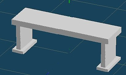
This tutorial will help you to take your first steps towards creating your own custom objects in MetasequoiaLE, by creating this simple bench.
Note
I have used
MetasequoiaLE R2.2 Beta, Version 1.2a can also be used, but drag handles
will not be available. And it will be more difficult to move objects
accurately.
If you make a mistake use CTL+Z to undo it.
When you start Meta the left side of the work area Should appear
like this.
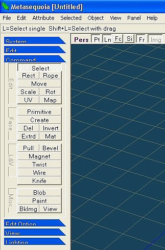
If the panel on the left is not visible, left click on the blue Command Tab to expand it. Ensure that only the Pt (show points) and the Ln (show lines) buttons just above the black workspace area are selected.
Creating the Top
Click the Primitive
button on the Command panel and a new Panel will open.
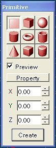
The flat square is selected by Default. If required checkmark the preview box and click the Property button, and a 2nd new panel opens.
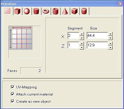
Enter 44.4 into the X size
box and 12.9 into the Z size box,
advance the X segment box to show 2.
This will divide the top of our bench into two segments making it easier
to texture. Make sure the Create as new object box is checked and close
this panel. Click the create button on the previous panel, the object
will appear in the workspace.
Now we need to give the top some
thickness, First click the select button on the Commands panel then
press Control + A on the keyboard to select your entire object. Click
the Extrd button on the Commands panel, a small panel with two options
will open, leave the normal option selected for now. We'll use the bevel
option later.
Position your cursor inside you object and left
Click & drag your mouse, to move a blue copy of your object about 0.5 Cm
above the original. Your object should now look like this.
You can right click & drag in the work area to rotate
the view if required.
As you can guess this is far too thick, so
we'll correct that next. Rotate the view until it's similar to this
screen shot.
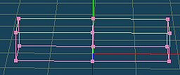
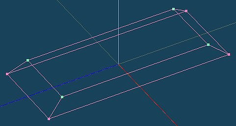
Click on a blank area of the workspace to deselect
everything. Now click select on the Command panel, holding down the
shift key click on the dots & lines forming the top half of the object
as shown here.
Click on Move on the Commands panel, once again a
new panel opens.
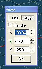
Make sure the Abs (Absolute) option is selected and
enter 4.7 into the Y box & click OK. Our top is now the correct
thickness. Click the small Fc (show faces) button near the top of the
workspace to view it in solid form.
Now would be a good time to
protect our work. Go to the top toolbar, select panel > object panel.
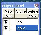
Click obj2 in order to select it, click the box just
to the left of it A key icon appears and the object can no longer be
edited. Click the eye icon to hide the object & clear the workspace.
Constructing the supports
Each support consists of two
parts a base and an upright. We are going to make one of each component,
then combine them into a new object and finally clone this new object to
give us two supports.
The base
If the show faces
button is still selected, click on it to deselect it. Using the create
Primitive panels create a flat base with these dimensions X=
5.2 Y = 12.9 leave both segment boxes
set to one.
Select all and open the Extrude options panel, by
clicking on the Select and Extrd buttons. This time we are going to use
the Bevel option, click bevel in the options panel to select it. Once
again click & drag to extrude the flat surface, as you can see the sides
of our base are now bevelled.
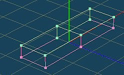
Rotate the view until you can
clearly see the four points, which mark the top corners of the base. It
may help to zoom in by left clicking & dragging on the magnifying glass
icon, just above the top right corner of the workspace.
Shift
click on each point to select it, the screen shot below show the correct
points.
Click on Move on the Commands panel, make sure the
Abs (Absolute) option is selected and enter 2.7 into the Y box & click
OK.Click the Fc (show faces) view it in solid form. Use the objects
panel to lock obj 3.
The upright
Open the create
Primitive panels and select the cube icon in either panel, create a cube
with these dimension's X= 3.7 Y=
16.88 Z = 11.4 leave all segment
boxes set to one, ensure the cube checkbox is not checked. Select all
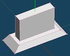
and bring up the move panel enter 14.1 into the Y field., click OK. The
upright has now moved into the correct position on the base. Using the
objects panel unlock obj 3.
Finishing & cloning the support
With only the base & support visible and unlocked, click the Misc
tab in the object panel. Scroll down and click �Merge all visible�
answer yes to the prompt., the base and support is now a single object.
(obj 4) Again on the objects panel click the clone tab, accept the
default settings and click OK. We now have two supports in exactly the
same place, (obj 1 and obj 4).
Putting it all together
In the objects
panel lock and hide object 4., and select obj 1 click select on the
Command panel. Then click one of the points at the top of the support.,
click move and note down the reading in the Y axis box .Just in case you
close the move panel by accident.
Lock obj 1, unlock & make
visible obj 2.( the bench top) if the move panel is still open check
the X value = 44.40 Z value
= 12.90 Note these values may be negative.
Enter the value
you noted down into the Y-axis box and click OK. With all objects
visible and obj �s 2 & 4 locked, select all.
Move the support
into position near one end of the bench, by dragging the red cone on the
drag handle or clicking and dragging the support. If you have dragged
the support you can position it exactly along the Z and Y-axis,
by entering these values into the move panel Z =
-8.71 Y = 14.1 and clicking OK.
Lock obj 4 and unlock obj 1. And move the other support into
position, once your Happy with the position of both supports, unlock all
of the objects and click on Misc merge all visible.
Exporting
your new creation
Click on File > Save as. Enter the filename
and folder you want to save to, in the save as type box choose, AutoCAD
(*dxf) , Set the Export options as shown below and click once on the
SWAP YZ button.
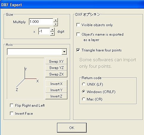
Multiply - 1.000
Digit = -1
Triangles have four
points box checked.